1. Product Overview
Plug valves are flow-control components used in cementing, fracturing, acidizing, and high-pressure manifold systems. They are mainly used for shutoff, flow regulation, and operational isolation in pup joints for high-pressure oilfield sites.
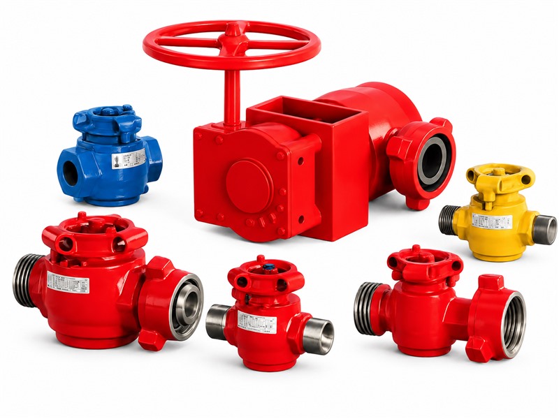
The product mainly consists of a valve body, plug, seal segments, bonnet, actuator, and related parts. Its compact structure and flexible operation meet sealing and stability requirements in high-pressure fluid-transfer systems.
The low-torque plug valve is forged from high-strength alloy structural steel. After strict heat treatment, it has a uniform metallographic structure and stable pressure-bearing capacity. Technical performance complies with relevant API Spec 6A requirements.
End connections include union connections, threaded connections (LP female thread and TBG male thread), and flange connections. Base-mounted configurations can also be supplied according to field manifold layout and installation requirements.
Common sizes cover 1 in, 2 in, 3 in, and 4 in. Cold working pressure ratings include 6,000 psi, 10,000 psi, 15,000 psi, and 20,000 psi. Standard, low-temperature, and sour-service products are available, together with matching plug valve repair kits.
2. Design Features
The plug valve uses a handwheel to rotate the plug, providing line shutoff and flow control. Seal segments between the valve body and plug, combined with precision machining and lapping, maintain reliable sealing under high-pressure service.
The pressure-containing structure is stable, with sufficient valve-body wall thickness and replaceable resilient NBR seals, making it suitable for pup joint systems.
Flexible connection options include union connections, LP threads, TBG threads, and other end forms, making the valve convenient for use with common high-pressure manifolds and replacement of imported products of the same type.
Maintenance is simple. Routine servicing does not require removing the complete valve from the line, and field maintenance does not require special tools.
The precision-machined plug and coated mating surfaces improve sealing performance, wear resistance, and corrosion resistance.
The plug cap has clear open/close position marks, and the detent spring assists positioning so operators can quickly identify valve status.
3. Plug Valve Main Technical Parameters
1. Main Parameters of Union-End Plug Valves
Working Pressure:6,000 psi~20,000 psi
Nominal Bore:1″~3″
Temperature Class: -29 ℃ to 121 ℃ (PU class)
-46 ℃~121 ℃ (PL class)
Service Condition: standard, low-temperature, and H2S service
Manufacturing Standard:API 6A & NACE MR0175
| Model | Specification | Working Pressure | Overall Dimensions | Connection Type | Actuator | Service Condition | ||
|---|---|---|---|---|---|---|---|---|
| L | A | H | ||||||
| 1" × 2" Fig 1502, 15,000 psi, F × M, Manual | 1″ | 15,000 psi | 268.2 | 61 | 185 | 2" Fig 1502 (F×M) | Manual | Standard |
| 1" × 2" Fig 1502, 15,000 psi, F × M, Pneumatic | 1″ | 15,000 psi | 268.2 | 61 | 185 | 2" Fig 1502 (F×M) | Pneumatic | Standard |
| 2" × 2" Fig 602, 6,000 psi, F × M, Manual | 2″ | 6,000 psi | 353 | 88 | 225.5 | Fig 602 (F×M) | Manual | Standard |
| 2" × 2" Fig 1002, 10,000 psi, F × M, Manual | 2″ | 10,000 psi | 353 | 88 | 225.5 | Fig 1002 (F×M) | Manual | Standard |
| 2" × 2" Fig 1502, 15,000 psi, F × M, Manual | 2″ | 15,000 psi | 353 | 88 | 225.5 | Fig 1502 (F×M) | Manual | Standard |
| 2" × 3" Fig 1502, 15,000 psi, F × M, Manual | 2″ | 15,000 psi | 374.5 | 88 | 225.5 | 3" Fig 1502 (F×M) | Manual | Standard |
| 2" × 2" Fig 1502, 15,000 psi, F × M, Pneumatic | 2″ | 15,000 psi | 353 | 88 | / | Fig 1502 (F×M) | Pneumatic | Standard |
| 2" × 2" Fig 1502, 15,000 psi, F × M, Hydraulic | 2″ | 15,000 psi | 353 | 100 | 409 | Fig 1502 (F×M) | Hydraulic | Standard |
| 2" × 2" Fig 2002, 20,000 psi, F × M, Manual | 2″ | 20,000 psi | 386 | 88 | 225 | Fig 2002 (F×M) | Manual | Standard |
| 3" × 3" Fig 602, 6,000 psi, F × M, Manual | 3″ | 6,000 psi | 432 | 103 | 254 | Fig 602 (F×M) | Manual | Standard |
| 3" × 3" Fig 1002, 10,000 psi, F × M, Manual | 3″ | 10,000 psi | 432 | 103 | 254 | Fig 1002 (F×M) | Manual | Standard |
| 3" × 3" Fig 1502, 15,000 psi, F × M, Manual | 3″ | 15,000 psi | 432 | 103 | 254 | Fig 1502 (F×M) | Manual | Standard |
| 3" × 3" Fig 1502, 15,000 psi, F × M, Gear-Operated | 3″ | 15,000 psi | 432 | 103 | 630 | Fig 1502 (F×M) | Gearbox | Standard |
| 3" × 3" Fig 1502, 15,000 psi, F × M, Hydraulic | 3″ | 15,000 psi | 432 | 103 | / | Fig 1502 (F×M) | Hydraulic | Standard |
| 3" × 3" Fig 2002, 20,000 psi, F × M, Manual | 3″ | 20,000 psi | 562 | 159 | 489 | Fig 2002 (F×M) | Manual | Standard |
| 3" × 3" Fig 2002, 20,000 psi, F × M, Gear-Operated | 3″ | 20,000 psi | 562 | 159 | / | Fig 2002 (F×M) | Gearbox | Standard |
| 3" × 3" Fig 2002, 20,000 psi, F × M, Hydraulic | 3″ | 20,000 psi | 562 | 159 | / | Fig 2002 (F×M) | Hydraulic | Standard |
| 1" × 2" Fig 1502, 10,000 psi, F × M, Manual, NACE | 1″ | 10,000 psi | 269 | 61 | 185 | 2" Fig 1502 (F×M) | Manual | H2S |
| 2" × 2" Fig 602, 6,000 psi, F × M, Manual, NACE | 2″ | 6,000 psi | 353 | 88 | 225.5 | Fig 602 (F×M) | Manual | H2S |
| 2" × 2" Fig 1502, 10,000 psi, F × M, Manual, NACE | 2″ | 10,000 psi | 353 | 88 | 225.5 | Fig 1502 (F×M) | Manual | H2S |
| 3" × 3" Fig 602, 6,000 psi, F × M, Manual, NACE | 3″ | 6,000 psi | 432 | 103 | 235 | Fig 602 (F×M) | Manual | H2S |
| 3" × 3" Fig 1502, 10,000 psi, F × M, Manual, NACE | 3″ | 10,000 psi | 432 | 103 | 235 | Fig 1502 (F×M) | Manual | H2S |
| 3" × 3" Fig 1502, 10,000 psi, F × M, Gear-Operated, NACE | 3″ | 10,000 psi | 432 | 103 | 630 | Fig 1502 (F×M) | Gearbox | H2S |
| 3" × 3" Fig 2202, 15,000 psi, F × M, Manual, NACE | 3″ | 15,000 psi | 562 | 159 | 489 | Fig 2202 (F×M) | Manual | H2S |
| 1" × 2" Fig 1502, 10,000 psi, F × M, Manual, Low-Temperature | 1″ | 10,000 psi | 269 | 178 | 185 | 2" Fig 1502 (F×M) | Manual | Low-Temperature |
| 2" × 2" Fig 602, 6,000 psi, F × M, Manual, Low-Temperature | 2″ | 6,000 psi | 353 | 201 | 225.5 | Fig 602 (F×M) | Manual | Low-Temperature |
| 2" × 2" Fig 1502, 10,000 psi, F × M, Manual, Low-Temperature | 2″ | 10,000 psi | 353 | 201 | 225.5 | Fig 1502 (F×M) | Manual | Low-Temperature |
| 3" × 3" Fig 602, 6,000 psi, F × M, Manual, Low-Temperature | 3″ | 6,000 psi | 432 | 103 | 235 | Fig 602 (F×M) | Manual | Low-Temperature |
| 3" × 3" Fig 1502, 10,000 psi, F × M, Manual, Low-Temperature | 3″ | 10,000 psi | 432 | 103 | 254 | Fig 1502 (F×M) | Manual | Low-Temperature |
2. Main Parameters of Threaded Plug Valves
Working Pressure:6,000 psi~15,000 psi
Nominal Bore:1″~3″
Temperature Class: -29 ℃ to 121 ℃ (PU class)
Manufacturing Standard:API 6A
Service Condition: standard service
| Model | Specification | Working Pressure | Overall Dimensions | Connection Type | Actuator | Service Condition | ||
|---|---|---|---|---|---|---|---|---|
| L | A | H | ||||||
| 1" × 2", 6,000 psi, 2" LP, Manual | 1″ | 6,000 psi | 232 | 45 | 185 | 2″ LP male thread | Manual | Standard |
| 1" × 2", 15,000 psi, 2" LP, Manual | 1″ | 15,000 psi | 232 | 61 | 185 | 2″ LP male thread | Manual | Standard |
| 1" × 2", 15,000 psi, 2" TBG, Manual | 1″ | 15,000 psi | 232 | 61 | 185 | 2″ TBG male thread | Manual | Standard |
| 2" × 2", 6,000 psi, 2" LP, Manual | 2″ | 6,000 psi | 218 | 76.5 | 198.3 | 2″ LP female thread | Manual | Standard |
| 2" × 2", 10,000 psi, 2" LP, Manual | 2″ | 10,000 psi | 218 | 76.5 | 198.3 | 2″ LP female thread | Manual | Standard |
| 2" × 2", 10,000 psi, 2" TBG, Manual | 2″ | 10,000 psi | 228 | 76.5 | 198.3 | 2″ TBG female thread | Manual | Standard |
| 3" × 3", 10,000 psi, 3" LP, Manual | 3″ | 10,000 psi | 316 | 110 | 314.5 | 3″ LP Female Thread | Manual | Standard |
3. Flanged Plug Valves and Base-Mounted Plug Valves
4. Example: 2" × 2" Fig 1502, 15,000 psi / 15,000 psi, F × M Plug Valve Exploded View and Parts List
| No. | Name | Quantity | No. | Name | Quantity | No. | Name | Quantity |
|---|---|---|---|---|---|---|---|---|
| 1 | Valve body | 1 | 8 | Locating pin | 2 | 15 | Bonnet O-ring | 1 |
| 2 | Sealing washer | 1 | 9 | Plug O-ring | 2 | 16 | Bonnet support ring | 1 |
| 3 | Spring retaining ring | 1 | 10 | Plug support ring | 2 | 17 | Spring dowel pin | 1 |
| 4 | Wing nut | 1 | 11 | Side seal segment | 2 | 18 | Valve body cover | 1 |
| 5 | Retaining ring | 3 | 12 | Segment seal ring | 2 | 19 | Plug cap | 1 |
| 6 | Detent spring | 1 | 13 | Seal segment | 2 | 20 | Lock nut | 1 |
| 7 | Stop pin | 2 | 14 | Plug | 1 | 21 | Grease fitting | 1 |
5. Plug Valve Repair Kit Parts List (Interchangeable with SPM Products of the Same Specification)
| No. | Part Name | 2″×2″ | 3″×3″ | No. | Part Name | 2″×2″ | 3″×3″ | No. | Part Name | 2″×2″ | 3″×3″ |
|---|---|---|---|---|---|---|---|---|---|---|---|
| 1 | Grease fitting | 2 | 1 | 4 | Plug | 1 | 1 | 7 | Segment seal ring | 2 | 4 |
| 2 | Plug O-ring | 2 | 2 | 5 | Bonnet O-ring | 1 | 1 | 8 | Seal segment | 2 | 2 |
| 3 | Plug support ring | 2 | 2 | 6 | Bonnet support ring | 1 | 1 | 9 | Side seal segment | 2 | 2 |
4. Operation and Maintenance Notes
Before use, check the nameplate pressure rating, bore size, connection type, and temperature range to ensure they match drilling, cementing, fracturing, or production service conditions.
The product has passed hydrostatic testing and nondestructive examination before shipment. After disassembly, repair, or seal replacement, hydrostatic testing must be performed again. The product may be put into service only after holding pressure for 10 minutes without leakage; air must be vented from the system before pressure testing.
Install and tighten hammer unions according to proper procedures. Avoid excessive hammering that may deform nuts or damage sealing faces. Operators should wear protective equipment.
Do not dismantle, tighten, or repair the valve while the system is under pressure. Never operate beyond the rated working pressure or the design temperature range of -46 ℃ to 121 ℃.
During service, regularly inspect the valve body, bonnet, plug, seal segments, and O-rings. If leakage, wear, corrosion, deformation, or difficult operation is found, clean, repair, or replace wearing parts promptly.
Avoid impact, rain exposure, and corrosive media during transportation and storage. Keep the product in a dry, ventilated area. Certificates, packing lists, and operating instructions are supplied with the product; special specifications can be ordered according to field service conditions.
