1. Product Overview
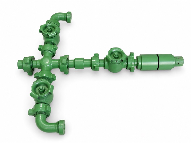
A well-test flowhead is installed at the top of a temporary test string. It interfaces with the rig elevators or hoisting arrangement, supports the suspended string load and provides surface flow and kill/circulation outlets. The catalogue labels “Top-Pull” and “Bottom-Pull” are retained only as configuration identifiers; the lift-sub, swivel and master-valve arrangement must be confirmed from the approved assembly drawing.
Available for standard service and sour service. For sour service, wetted metallic materials are selected for the specified environment in accordance with NACE MR0175/ISO 15156.
The catalogue overview states 2 in, 2 1/2 in and 3 in with rated working pressure from 6,000 psi to 15,000 psi; the displayed model table lists 10,000 and 15,000 psi configurations. Other ratings require an approved assembly drawing and test record.
2. Design Features
The assembly provides separate flow-wing and kill/circulation paths and may incorporate a handling/lift sub and swivel, as shown on the approved configuration drawing.
The catalogue gives an axial load capacity of 1,500 kN to 2,000 kN; the allowable suspended load must be confirmed for the specific connection, pressure, bending-load and temperature combination.
Each assembly is subjected to hydrostatic pressure and sealing tests at the pressures and hold times specified in the approved test procedure.
The compact, lightweight design simplifies transportation and field installation.
3. Well Test Flowhead Main Technical Parameters
| Model / Configuration | Rated Working Pressure | Catalogue Configuration | Side-Outlet Connection | Lower-Sub Connection | Service |
|---|---|---|---|---|---|
| 2" Fig 1002, 10,000 psi, Bottom-Pull Type | 10,000 psi | “Bottom-Pull”—confirm arrangement drawing | 2" Fig 1002 | Drill-pipe or TBG tubing thread, as specified on the approved drawing | Standard |
| 2" Fig 1502, 10,000 psi, Bottom-Pull Type, NACE | 2" Fig 1502 | Sour service* | |||
| 2" Fig 1502, 15,000 psi, Bottom-Pull Type | 15,000 psi | Standard | |||
| 2 1/2" Fig 1502, 10,000 psi, Top-Pull Type | 10,000 psi | “Top-Pull”—confirm arrangement drawing | 2" Fig 1502 | Standard | |
| 2 1/2" Fig 1502, 15,000 psi, Top-Pull Type | 15,000 psi | Standard |
* Sour-service suitability requires environmental data and documented material selection in accordance with NACE MR0175/ISO 15156; a model label alone is not evidence of suitability.