1. Product Overview
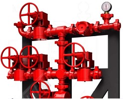
The cementing manifold collects cementing-pump discharge and routes cement slurry to the selected wellhead line while providing defined isolation and switching points.
The manifold usually consists of pup joints, plug valves, flanged or union connectors, and support structures, configured around the wellsite layout, pressure rating, and connection specification.
Built for land and offshore cementing operations, the manifold supports high-pressure transfer, distribution, and flow switching of cement slurry, clean water, and similar media.
2. Design Features
Plug valves provide on/off isolation for process switching during cementing. They are not used as throttling or pressure-regulating devices unless the specific valve design is expressly qualified for that duty.
Manifold layout and end connections are selected to interface with cement-pump discharge iron, wellhead equipment and the specified pup joints; API 6A flanged interfaces are used only where documented for the ordered configuration.
Pressure-containing components are selected for the stated cement-slurry pressure, temperature, solids loading and abrasive duty. Valve access and isolation points are arranged to support flushing, inspection and maintenance after depressurization.
3. Cementing Manifold Main Technical Parameters
| Parameter / Model | GG-35 | GG-70 | GG-105 |
|---|---|---|---|
| Rated Working Pressure | 5,000 psi (35 MPa) | 10,000 psi (70 MPa) | 15,000 psi (105 MPa) |
| Nominal Bore | 2 in to 3 in | ||
| Rated Operating-Temperature Range | Order-specific; verify the product temperature class and the documented material/seal limits. Do not infer a combined API “L–U” class. | ||
| Connection Type | Specified API Spec 6A flanged end or hammer-union end | ||
| Service | Standard or low-temperature, as documented for the ordered configuration | ||
| Applicable Requirements | Project/manufacturer specification; API Spec 6A only for specified flanged interfaces/components | ||