1. Product Overview
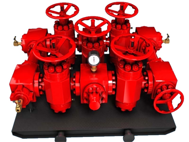
The well test choke manifold is installed in the surface well-test flowline to regulate flow through a selected choke and to support pressure and temperature measurement for flow-rate and well-deliverability evaluation.
The manifold uses replaceable fixed-size choke beans, or another specified choke arrangement, to control test flow rate and downstream pressure during surface well testing.
Flanged connections and slab gate valves are selected for the stated pressure, temperature, erosion duty and well-test fluid composition.
Common nominal bores range from 2 1/16 in to 4 1/16 in. The stated operating-temperature range is -29 °C to 121 °C, subject to the documented material and seal configuration. For sour service, wetted metallic materials are selected for the specified environment in accordance with NACE MR0175/ISO 15156.
2. Design Features
Flanged connections provide reliable integration with wellhead and test-line systems.
The outlet can use a union connection for quick field line installation and dismantling.
Forged flanged crosses may incorporate instrument take-offs for pressure monitoring; the port rating, thread/interface and instrument isolation arrangement must be specified.
Fixed-bean or adjustable choke configuration is selected for the required test rate, pressure drop, fluid phase, solids loading and control method.
3. Well Test Choke Manifold Main Technical Parameters
| Model | Rated Working Pressure | End Connection |
|---|---|---|
| YZG-42-3 | 6,000 psi (42 MPa) | 3″ Fig 602 |
| YZG-70-3 | 10,000 psi | 3″ Fig 1002 |
| YZG-105-4 | 15,000 psi | 4″ Fig 1502 |
| YZG-35-80 | 5,000 psi | 3 1/8 in API 6A flange, 5,000 psi |
| YZG-70-78 | 10,000 psi | 3 1/16 in API 6A flange, 10,000 psi |
| YZG-105-78 | 15,000 psi | 3 1/16 in API 6A flange, 15,000 psi |
| YZG-35-103 | 5,000 psi | 4 1/16 in API 6A flange, 5,000 psi |
| YZG-70-103 | 10,000 psi | 4 1/16 in API 6A flange, 10,000 psi |
| YZG-105-103 | 15,000 psi | 4 1/16 in API 6A flange, 15,000 psi |