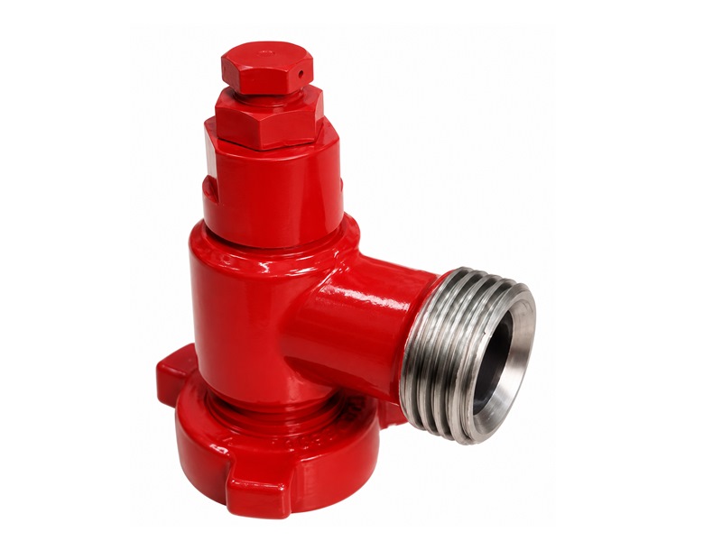
1. Product Overview
The pressure relief valve is direct-acting and self-resetting. Its release mechanism uses a spring-loaded steel ball and seat. When system pressure exceeds the set value, the valve opens automatically to relieve pressure; after pressure returns to a safe range, the stem resets under spring force and closes.
The product can be installed on high-pressure flow-control lines, reciprocating plunger pumps, pressure-pumping manifold skids, and cementing or fracturing equipment to limit maximum system pressure and protect equipment and personnel.
The top adjustment mechanism sets unloading pressure according to field service conditions. The adjustment range covers 5,000 psi to 20,000 psi, meeting protection requirements for pup joints with different pressure ratings.
The valve body is forged from high-quality alloy structural steel, providing good pressure-bearing strength and impact resistance for long-term use in high-pressure oilfield service.
2. Design Features
The spring-loaded structure provides automatic opening and closing, enabling rapid unloading during abnormal overpressure and continuous protection without shutdown.
The compact valve-body structure and simple flow-path and sealing design provide reliable sealing under normal operation and easy installation in high-pressure pump units and line systems.
The top adjustment mechanism supports continuous pressure setting, allowing accurate unloading pressure adjustment to match different job pressure ratings.
Union connections make installation, dismantling, and field replacement convenient. Connection types and sizes match common pup joint systems.
Manufactured to relevant API 6A requirements, Fig 1502, Fig 2002, and other connection specifications can be used with similar products and provide strong interchangeability.
With few wearing parts and low maintenance requirements, the valve is suitable as an overpressure protection component for cementing, fracturing, and high-pressure fluid-service equipment.
3. Pressure Relief Valve Main Technical Parameters
Working Pressure:6,000 psi~20,000 psi
Nominal Bore: 2 in
Temperature Class: -29 ℃ to 121 ℃ (PU class)
| Model | Cold Working Pressure | L | A | H | End Connection Type | Connection Type |
|---|---|---|---|---|---|---|
| 2" Fig 1502, 15,000 psi, F × M | 15,000 psi | 366 | 154 | 154 | Fig 1502 | F × M |
| 2" Fig 2002, 20,000 psi, F × M | 20,000 psi | 376 | 166.5 | 154 | Fig 2002 | F × M |
4. Pressure Relief Valve Repair Kit
The repair kit is used for seal maintenance and wearing-part replacement on pressure relief valves. It mainly includes the spring-seat O-ring, stem, stem seal, stem O-ring, steel ball, seat, and seat O-ring.
