1. Product Overview
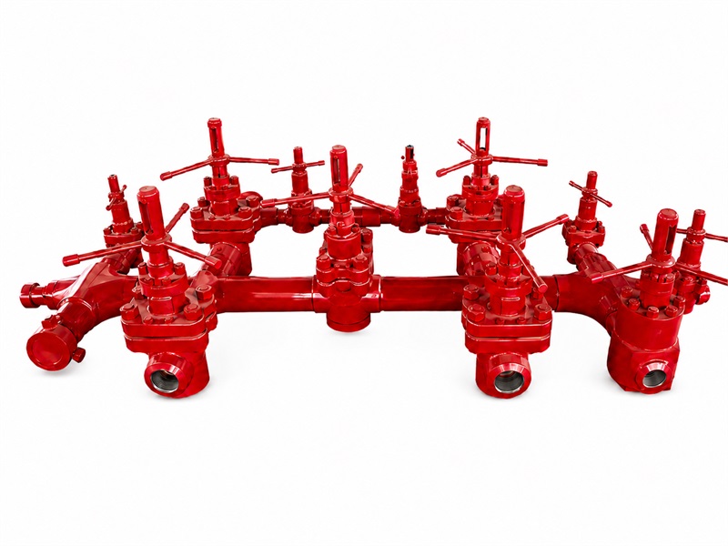
The high-pressure drilling fluid manifold supports high-pressure jet drilling by collecting, distributing, and transferring drilling fluid discharged from multiple mud pumps.
The system usually includes a mud-pump discharge manifold and a standpipe manifold. The pump manifold combines and routes the high-pressure pump discharge, while the standpipe manifold directs drilling fluid to the selected standpipe or drill-floor service line. The standpipes, rather than the manifold itself, carry drilling fluid vertically up the derrick.
With high-pressure valve assemblies selecting and isolating the flow path, drilling fluid is routed to the standpipe, through the drilling hose and top drive or swivel, and then down the drillstring for normal circulation and other approved fluid-routing operations.
2. Design Features
The pump manifold collects high-pressure discharge fluid from multiple mud pumps and distributes it according to service conditions, enabling line switching, inspection, and maintenance during continuous drilling operations.
The standpipe manifold selects and isolates the discharge route to the required standpipe or drill-floor service line; the standpipe itself carries drilling fluid vertically up the derrick.
A full-bore or constant-bore flow path, where specified, supports high flow rates and helps limit turbulence and vibration. API 6A flanged and union-end connections support field installation, dismantling, and maintenance.
A clearly identified valve line-up supports route verification, isolation and maintenance. The approved layout must also address erosion, vibration, pipe support, access and trapped-pressure bleed-down.
3. High-Pressure Drilling Fluid Manifold / Standpipe Manifold Main Technical Parameters
| Parameter / Model | ZG-35/LG-35 | ZG-70/LG-70 |
|---|---|---|
| Rated Working Pressure | 5,000 psi (35 MPa) | 10,000 psi (70 MPa) |
| Nominal Bore | 2 in to 5 in | |
| Rated Operating-Temperature Range | Order-specific; verify the product temperature class and the documented material/seal limits. Do not infer a combined API “L–U” class. | |
| Connection Type | API Spec 6A flanged end or specified hammer-union end | |
| Service | Standard or low-temperature; sour service only when the environment and material configuration are specified | |
| Applicable Requirements | SY/T 5524 where contractually specified; API Spec 6A for specified flanged interfaces/components; NACE MR0175/ISO 15156 for sour-service metallic-material selection | |