1. Product Overview
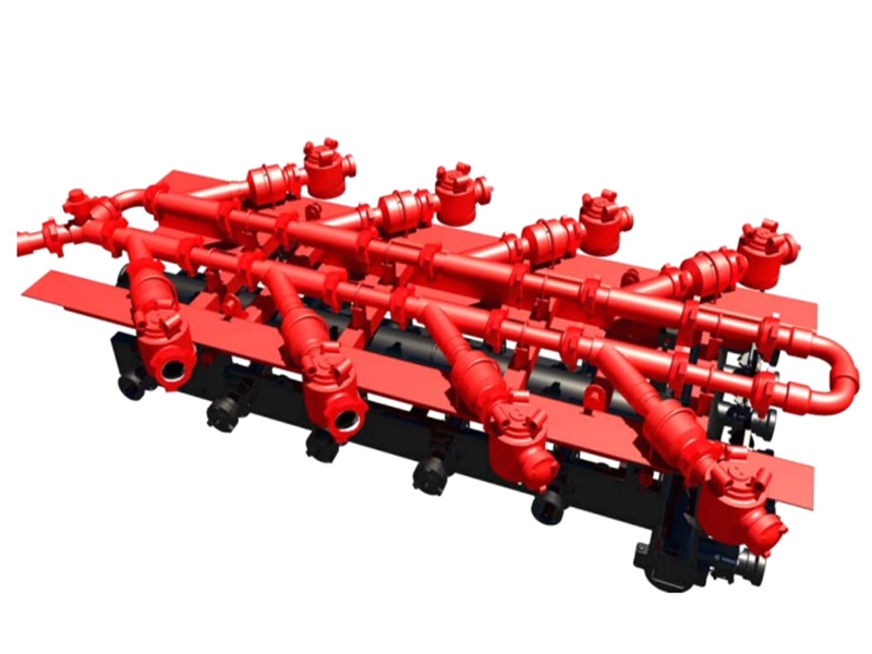
The fracturing manifold handles fracturing-fluid transfer, gathering, and high-pressure discharge, connecting blending equipment, fracturing pump units, and the wellhead.
The combined high-/low-pressure manifold integrates low-pressure gathering, low-pressure distribution, and high-pressure gathering functions for faster rig-up, relocation, and space-saving field layouts.
The catalogue term “Additive-Feeding Manifold” is retained as a neutral label. The actual medium—such as liquid chemical, proppant-related stream, balls/plugs or another additive—and its pressure level must be defined by the process drawing.
The pump discharge manifold gathers and transfers flow from the high-pressure discharge side of fracturing pump units and can be configured by flow rate, pressure rating, and connection form.
2. Design Features
Fracturing manifolds are configured around the fracturing workflow, covering low-pressure gathering, high-pressure distribution, additive-feeding control, and pump discharge gathering for integration with blenders, fracturing pump units, and wellhead equipment.
The high-pressure section uses pressure-containing components selected for the stated CWP, erosion duty and connection profile. Union-end or flanged connections are specified by the approved layout.
Where plug valves are used in an additive-feeding subsystem, they provide on/off isolation and switching; they are not throttling devices unless expressly qualified. Pump-discharge manifolds are configured by total flow rate, pressure rating and connection direction.
A modular layout can reduce field connections, but the final arrangement must be checked for line restraint, erosion, valve access, pressure isolation and safe bleed-down.
3. Fracturing Manifold Main Technical Parameters
| Combined High-/Low-Pressure Manifold Main Technical Parameters | ||||
|---|---|---|---|---|
| Parameter / Model | GDZG-42 | GDZG-70 | GDZG-105 | GDZG-140 |
| Cold Working Pressure | 6,000 psi | 10,000 psi | 15,000 psi | 20,000 psi |
| High-Pressure Section Nominal Bore | 2 in to 3 in | |||
| Low-Pressure Section Nominal Bore | 8 in to 12 in | |||
| Additive-Feeding Manifold Main Technical Parameters | |||
|---|---|---|---|
| Parameter / Model | TLG-42 | TLG-70 | TLG-105 |
| Cold Working Pressure | 6,000 psi | 10,000 psi | 15,000 psi |
| Nominal Bore | 2 in to 3 in | ||
| Feeder Capacity | 20 L to 50 L | ||
| Feeding Method | Single-wing or dual-wing | ||
| Pump Discharge Manifold Main Technical Parameters | |||
|---|---|---|---|
| Parameter / Model | BPG-35 | BPG-70 | BPG-105 |
| Cold Working Pressure | 5,000 psi | 10,000 psi | 15,000 psi |
| Nominal Bore | 2 in to 3 in | ||