1. Product Overview
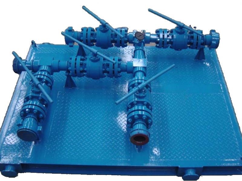
The diverter manifold routes oil, gas, and water during production well testing. Installed downstream of the separator, it directs choked and separated media to metering or storage equipment.
Separated liquids or gas can be routed to metering tanks, storage tanks, or tank trucks according to the field process, supporting fluid metering and process switching during testing.
The displayed model table lists 750 psi and 1,000 psi configurations with 3 in and 4 in connections. Any 2,000 psi or other configuration requires confirmation from the approved product drawing and pressure-test documentation.
Configurations are selected for the well-test process, connection type, pressure rating and field layout. API Spec 16C compliance is not claimed for this downstream test-separator service.
2. Diverter Manifold Main Technical Parameters
| Model | Rated Working Pressure | End Connection |
|---|---|---|
| FLGH-5-3 | 750 psi | 3″ Fig 200 |
| FLGH-7-3 | 1,000 psi | |
| FLGH-7-3 | 3″ Fig 602 | |
| FLGH-7-3 | 3″ Fig 1502 | |
| FLGH-7-4 | 4″ Fig 200 | |
| FLGH-7-4 | 4″ Fig 602 |