1. Product Overview
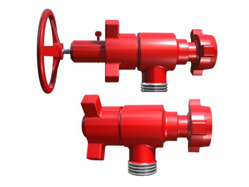
High-pressure choke valves are used for flow regulation, pressure control, and throttling pressure reduction in high-pressure lines and manifold systems. They provide stable control of fluid flow and line pressure by changing the flow area.
Structural types include positive choke valves and adjustable choke valves. Adjustable structures can be selected as needle type, sleeve type, or orifice-plate type. By operating mode, they are available in manual and hydraulic types.
Adjustable choke valves change the flow area through stem cone movement, plunger movement, or orifice plate rotation. Positive choke valves control flow and pressure by changing the fixed bean size.
The company supplies 2 in to 4 1/16 in products. Connection types include union-end and flanged connections. Working pressure covers 5,000 psi to 20,000 psi, suitable for cementing, fracturing, drilling-fluid circulation, and high-pressure manifold applications.
2. Design Features
The flow-adjustment position can be read directly from the scale, allowing operators to quickly judge valve opening and adjustment status on site.
Key parts such as choke beans, stem tips, and seats use hard alloy or tungsten carbide materials to improve erosion, wear, and corrosion resistance.
The cylindrical stem structure helps improve flow condition, reduce line vibration and noise, and increase stability during high-pressure choking.
The valve body and outlet flange use a split structure, making seat inspection, replacement, and field maintenance easier.
Union and flange connection dimensions match common high-pressure manifold systems for field installation, replacement, and matching use.
Fixed choke beans use inch specifications, making them suitable for common high-pressure flow-control equipment and standardized spare-parts management.
3. Choke ValveMain Technical Parameters
| Model | Specification | Working Pressure | Overall Dimensions | Connection Type | Adjustment Type | Service Condition | |
|---|---|---|---|---|---|---|---|
| 2" Fig 1502, 15,000 psi, F × M, Fixed Choke Bean | 2 ″ | 15,000 psi | 154 | 206 | Fig 1502 (F×M) | Fixed Choke Bean | Standard |
| 2" Fig 1502, 15,000 psi, F × M, Needle Adjustment | 2 ″ | 15,000 psi | 154 | 206 | Fig 1502 (F×M) | Needle Adjustment | Standard |
| 3" Fig 1502, 15,000 psi, F × M, Needle Adjustment | 3 ″ | 15,000 psi | 243 | 243 | Fig 1502 (F×M) | Needle Adjustment | Standard |
| 2 1/16" API 6A Flange, 5,000 psi, Sleeve Adjustment | 2 1/16″ | 5,000 psi | 214 | 214 | 2 1/16″ -5,000 psi-API 6A Flange | Sleeve Adjustment | Standard |
| 2 1/16" API 6A Flange, 5,000 psi, Needle Adjustment | 2 1/16″ | 5,000 psi | 203 | 175 | 2 1/16″ -5,000 psi-API 6A Flange | Needle Adjustment | Standard |
| 2 1/16" API 6A Flange, 10,000 psi, Needle Adjustment | 2 1/16″ | 10,000 psi | 225 | 195 | 2 1/16″ -10,000 psi-API 6A Flange | Needle Adjustment | Standard |
| 2 1/16" API 6A Flange, 15,000 psi, Needle Adjustment | 2 1/16″ | 15,000 psi | 262 | 226 | 2 1/16″ -15,000 psi-API 6A Flange | Needle Adjustment | Standard |
| 2" Fig 2002, 20,000 psi, F × M, Needle Adjustment | 2 ″ | 20,000 psi | 205 | 240 | Fig 2002 (F×M) | Needle Adjustment | Standard |
| 2 9/16" API 6A Flange, 10,000 psi, Needle Adjustment | 2 9/16″ | 10,000 psi | 298 | 264 | 2 1/16″ -10,000 psi-API 6A Flange | Needle Adjustment | Standard |
| 2 9/16" API 6A Flange, 15,000 psi, Needle Adjustment | 2 9/16″ | 15,000 psi | 298 | 267 | 2 1/16″ -15,000 psi-API 6A Flange | Needle Adjustment | Standard |
| 3 1/8" API 6A Flange, 5,000 psi, Needle Adjustment | 3 1/8″ | 5,000 psi | 289 | 226 | 3 1/8″ -5,000 psi-API 6A Flange | Needle Adjustment | Standard |
| 3 1/16" API 6A Flange, 10,000 psi, Needle Adjustment | 3 1/16″ | 10,000 psi | 298 | 264 | 3 1/16″ -10,000 psi-API 6A Flange | Needle Adjustment | Standard |
| 3 1/16" API 6A Flange, 15,000 psi, Needle Adjustment | 3 1/16″ | 15,000 psi | 295 | 264 | 3 1/16″ -15,000 psi-API 6A Flange | Needle Adjustment | Standard |
| 3" API 6A Flange, 15,000 psi, Sleeve Adjustment | 3 ″ | 15,000 psi | 240 | 312 | 3 1/16″ -15,000 psi-API 6A Flange | Sleeve Adjustment | Standard |
| 4 1/16" API 6A Flange, 5,000 psi, Sleeve Adjustment | 4 1/16″ | 5,000 psi | 298 | 264 | 4 1/16″ -5,000 psi-API 6A Flange | Sleeve Adjustment | Standard |
| 4 1/16" API 6A Flange, 10,000 psi, Needle Adjustment | 4 1/16″ | 10,000 psi | 292 | 252 | 4 1/16″ -10,000 psi-API 6A Flange | Needle Adjustment | Standard |
4. Choke Valve Structure Diagram
① O-ring I ② Washer ③ Support ring ④ Composite seal ring ⑤ Seal retaining ring ⑥ O-ring II ⑦ O-ring support ring
Working Pressure:5,000 psi~20,000 psi
Nominal Bore:2″~3″
Temperature Class:-29 ℃~121 ℃ (PU class)
Manufacturing Standard:API 6A,API 16C
